CNC Router
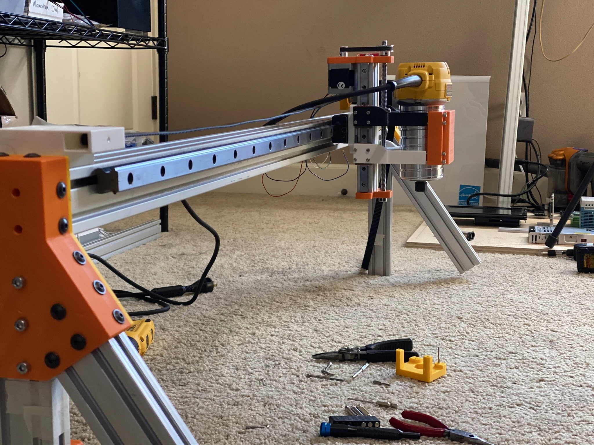
An affordable, fully-functional CNC router on a sliding gantry platform for routing and carving across a 4’ x 8’ working area with a 3” cut depth.
What is It?
An affordable CNC router designed around a readily available, hand-held tool using a combination of custom 3-D printed parts and commercially available materials.
Get the plans, specs, and bill of materials HERE.
How Does it Work?
Built on a sliding gantry system, the router is positioned on a cross beam mounted on tracks running the length of the frame with motors to control movement along the X and Y axes. The router secured in a custom designed housing, with precise motor control for movement on the Z axis to determine cut depth while holding the router steady to produce clean, precise carving.
The system is connected to a laptop running a control application to design and execute routing and carving.
Backstory
When my wife encountered difficulty routing a blind pocket to make a box for her D&D dice, I saw an opportunity to create an affordable home CNC routing system so she could complete her carpentry projects and keep all her fingers intact.
Initially, we considered purchasing a CNC routing system, but after looking at various low(er) cost options, including control software, we determined we could make something with better functionality that was still within our target budget. The build is a combination of 3D printed parts designed in SolidWorks, various extruded aluminum framing we had on hand, some linear rails and bearings from an old project, and other widely available parts sourced from Amazon.com and McMaster.com.
We started at the end(effector), and built around the DeWalt DWP611 router I gave Melissa as a gift last December. This is the same tool several commercially available CNC machines use, so it seemed like the reasonable choice to mount at the business end.
We knew we wanted to be able to fit at least a 4’ x 8’ standard sized sheet of material into the machine, and be able to cut to a depth of approximately 75 mm (about 3”). These basic parameters gave us a good place to start and so I started designing a Z-axis mechanism to hold and control the router cut depth.
To frame a bench into which the mechanics and electronics would be built, we needed to decide how big the linear rails and bearings would be and how the three orthogonal axes would be mounted. Some high end systems mount two axes on a sliding gantry, a moving bridge whose sides straddle the working platform, and the design allows the system provides a large working area to produce larger finished pieces.
We decided on a similar sliding gantry arrangement, although we wanted to go with a left handed coordinate system rather than the right handed type shown in the image above.
To accelerate development, we worked in parallel. While I prototyped the mechatronic elements in the lab, Melissa designed and built the bench in the workshop.
Once the major parts for each axis were designed and fabricated, we assembled the large X-axis frame in the workshop. We squared the X-axis frame corners and mounted the Y-axis gantry, then we attached the Z-axis, which holds the router, to the gantry.
Everything looked good, and proceeded to the fit-check using woodworking clamps to temporarily hold everything in place while we checked the dimensions. The fit looked good, with a 5mm gap between the sides of the bench and the aluminum frame for the mechanism as planned.
Next, I designed and assembled the electronics needed to drive the system and run the control software. I’ve had contract firms create neat, tidy, functional machine control systems on DIN rails for several professional projects, but I had never previously wired a panel myself. I did a little research and put into practice what I’ve learned from those great companies over the years.
I did some arranging to create a workable layout on the bench, and then mounted everything to a plywood panel to fit inside the machine frame.
Creating a safety cut-out system to stop all movement and the spinning cutter was critical, so I prioritized building this critical safety feature into the bench. Since I feel strongly about aesthetics and functionality, I worked to create a clean, functional, and elegant mechanism, with its own power and switching system, built into the heart of the circuit.
Once the electronics were thoroughly tested in the lab, I connected the motors on the mechanism and ran tests to determine key parameters, like the number of steps per millimeter, safe maximum speed, and the functional limits along each axis.
Once all parameters were finalize, we generated a test file and performed the first cuts with our new CNC routing system. Everything worked as expected and my wife is excited about future projects featuring safe carving and routing.
Adding finishing touches to a project often takes longer than anticipated. With this in mind, we developed our finishing plan early on and ordered the needed materials, such as paint, cupboard doors, hinges, and cable mounts, as soon as the fit-check was completed. However, the Covid-19 pandemic created some hitches in this plan and, despite ordering things early, quite a lot of our finishing materials arrived weeks later than anticipated. As a result, our finishing efforts are moving in fits and starts as deliveries arrive.
Pending - finished images and description


